
DARREN FORSCHINO
Home / Case 02 — Journey to 10,000 ft
Journey to 10,000 ft · Syracuse University Senior Capstone

High-Power Rocket
Development.

A five-person senior capstone project to design, build, and flight-test a high-power rocket targeting a ~10,000-ft mission. Budget was the first-order constraint and drove the vehicle architecture; packaging and schedule followed from that decision.

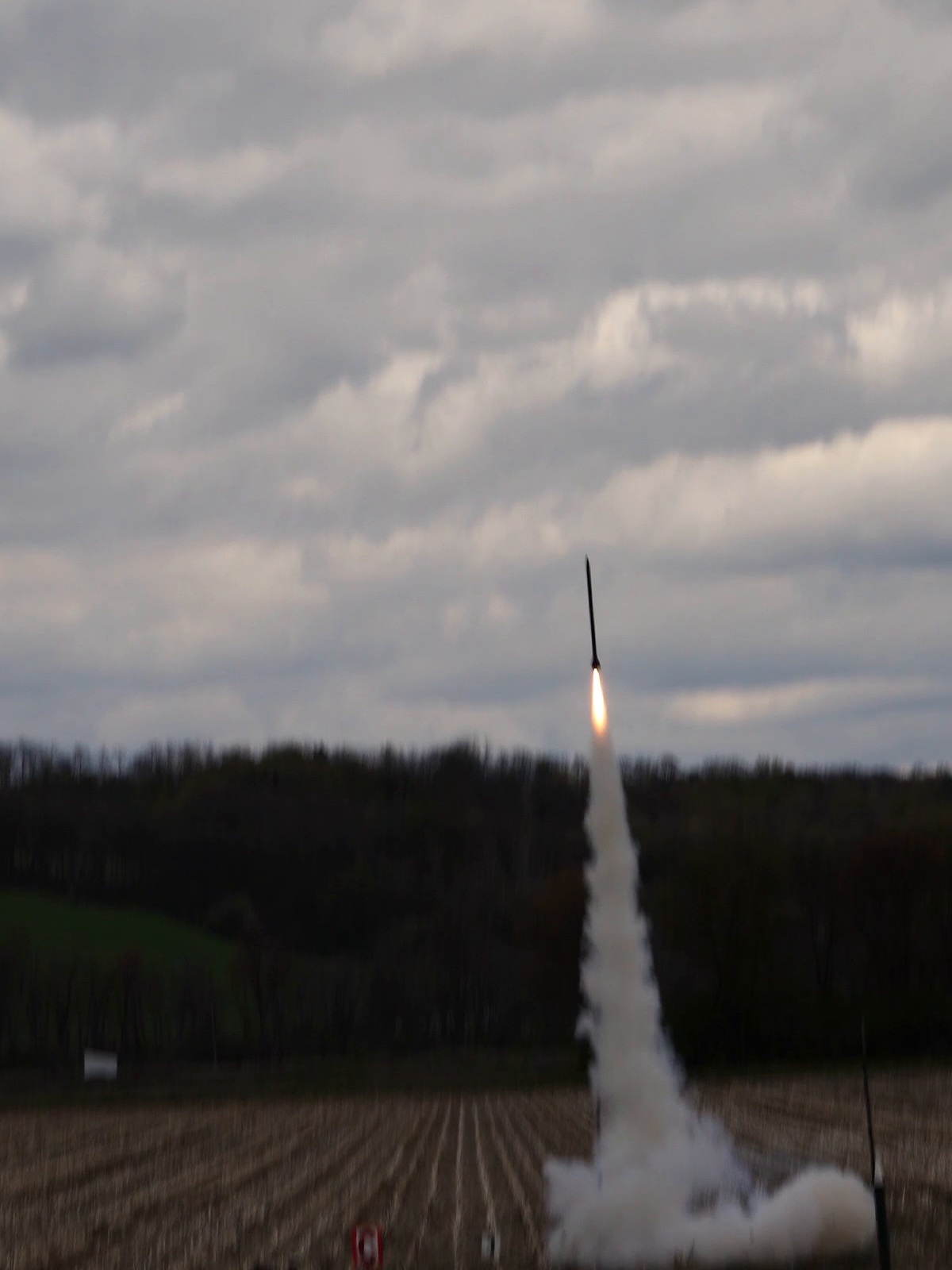
FIG. 00 · HeroFSV — Flight Test
Full-scale vehicle in flight.
FSV under thrust · frame from actual flight test.
Full-scale vehicle in flight, plume visible above the launch site
Role
Avionics, Flight Software & Mechanical Integration
Team
Five students
Institution
Syracuse University
Vehicles
3 (SSV-I, SSV-II, FSV)
Target
~10,000 ft altitude
§ 01 — Mission & Constraints
The problem, before the design
MISSION & ARCHITECTURE ORIGIN

Budget was the first-order architectural driver.

Early in the project the team evaluated carbon-fiber and fiberglass airframe options. Larger-diameter composite airframes carried a steep cost premium relative to the team’s budget, which pushed the design toward a minimum-diameter architecture: an airframe only slightly larger than the motor.

The team later transitioned to kraft phenolic, which reduced the original diameter-related material cost pressure. By that point the vehicle architecture and subsystem designs had already developed around minimum diameter, and that inherited architecture stayed with the project through flight test.

The consequences propagated through the system: constrained avionics packaging, constrained recovery volume, more difficult mechanical interfaces, and reduced integration margin.

FIG. 01Architecture-origin chain
LIMITED BUDGET
STEEP COST PREMIUM ON LARGER COMPOSITE AIRFRAMES
MINIMUM-DIAMETER ARCHITECTURE
↓  material later changed to kraft phenolic — architecture retained
TIGHT INTERNAL PACKAGING
DOWNSTREAM AVIONICS · RECOVERY · MECHANICAL CONSEQUENCES
Causal, not aerodynamic. Lower drag and lower structural mass were secondary benefits, not the primary reason for the architecture.
MAJOR CONSTRAINTS
BUDGET

The primary constraint. Made larger composite airframes cost-prohibitive and drove the shift to a minimum-diameter architecture.

PACKAGING

Minimum-diameter airframe created severe internal-volume constraints for every subsystem.

MASS / DRAG

The vehicle had to deliver enough performance for the target altitude on a commercially available motor.

RECOVERY

Safe, reliable recovery of a high-energy vehicle back to the ground.

SCHEDULE

A capstone development timeline that had to include multiple flight-test iterations.

EXPERIENCE

The team was developing high-power rocketry experience while building the vehicle.

§ 02 — My Primary Contributions
Individual, not team
A

Avionics & Embedded Software

  • Teensy-based flight electronics
  • IMU + barometric sensing
  • Onboard data acquisition
  • Embedded firmware
  • BlueJay altimeter integration
  • Recovery electronics
  • Experimental servo control
B

Flight Data & Analysis

  • Data collection
  • Consolidation across sensors
  • Post-flight analysis
  • Failure diagnosis support
  • Initial trajectory hand calcs
C

Mechanical Design

Personally designed
  • Avionics pod
  • Payload housing
  • Motor casing / housing
  • Motor-retention system
D

Hardware Integration

  • Avionics assembly
  • Motor retention
  • Recovery assembly
  • Parachute connections
  • Nylon webbing
  • Recovery deployment integration
  • Machining & assembly
E

Flight Testing

Heavily involved in preparation, execution, troubleshooting, and post-flight analysis of all three major development flights.

Overall vehicle architecture, aerodynamic design, and flight operations were team-level efforts.
§ 03 — Annotated System Overview
Where my work sat in the vehicle
FIG. 02 · Full-scale vehicle configurationOpenRocket
Full-scale vehicle OpenRocket configuration alongside the finished airframe
5
2
3
3
1
4
OpenRocket component layout above · finished FSV airframe below. Callouts (1–5) below map to subsystems; aft fins (5) SSV-II only.CONFIG
1
Payload
Designed the payload housing.
2
Avionics
Avionics pod, electronics, embedded firmware, sensors, and data acquisition.
3
Recovery
Significant assembly and integration, including deployment electronics and connections.
4
Propulsion
Motor casing and retention architecture.
5
Control Surfaces — SSV-II ONLY
Mechanical and software integration for the servo-driven aft-fin deflectors. Removed from the full-scale vehicle after flight test.
§ 04 — Avionics Deep Dive
Primary area of ownership
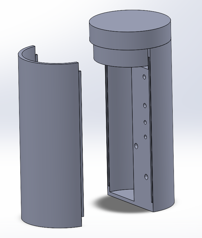
Avionics pod CAD — two-piece housing
FIG. 03.A · Avionics pod — CAD (SolidWorks)CAD
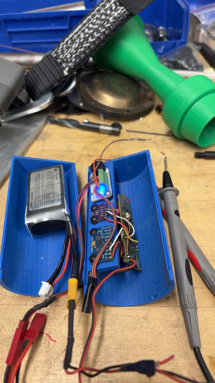
Avionics pod under power at the bench during integration checkout
FIG. 03.B · Avionics pod — powered bench checkoutPHOTO

An embedded architecture inside a minimum-diameter tube.

I owned most of the avionics and embedded coding effort: integrating and programming Teensy-based flight electronics, adding IMU and barometric sensing, developing the data-collection firmware, and integrating a BlueJay altimeter for recovery deployment and redundant data.

The avionics pod was both an electrical and a mechanical problem: the same volume had to hold sensors, storage, power, deployment interfaces, and the payload housing structure.

Framing
Developed and integrated an embedded flight-data and control architecture inside a tightly constrained rocket avionics package — combining inertial and barometric sensing, onboard data acquisition, recovery interfaces, and experimental servo-actuated flight controls.
FIG. 04Avionics architecture
SENSE
IMU
Barometer
BlueJay altimeter
COMPUTE
Teensy MCU
Data storage
Flight-state logic
ACT
Servo outputs*
Recovery deployment
Recovery deployment interface
POWER
Battery + regulation
REDUNDANCY
Independent data path via BlueJay
* Servo outputs used on SSV-II only.
FIG. 05Simplified flight-state logic
IDLE
ARMED
BOOST
COAST
APOGEE
DEPLOY
DESCENT
LANDED
Simplified state diagram. Actual transitions gated on IMU + barometer thresholds and altimeter events.
§ 05 — Mechanical Integration Under Severe Packaging Constraints
Working inside the inherited architecture
EXAMPLE 01

Avionics Packaging

The avionics pod was the clearest instance of the inherited architecture forcing electrical and mechanical design to solve the same problem simultaneously. Sensors, storage, power, deployment interfaces, and the payload housing structure had to share a single small internal volume — a direct consequence of the minimum-diameter decision.

See § 04 — Avionics Deep Dive for the CAD and installed hardware.

EXAMPLE 02

Motor Retention

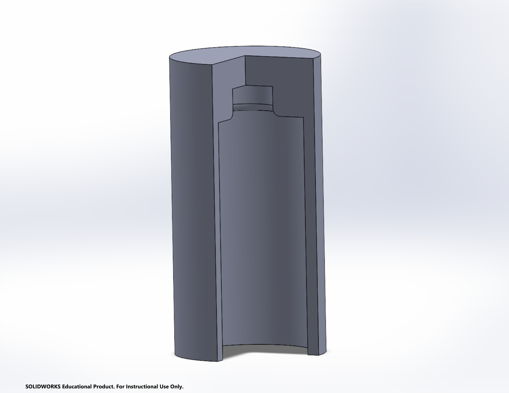
Design problem: secure the motor to the vehicle, keep unnecessary mass out, fit the constrained aft geometry, and remain manufacturable with available shop resources.

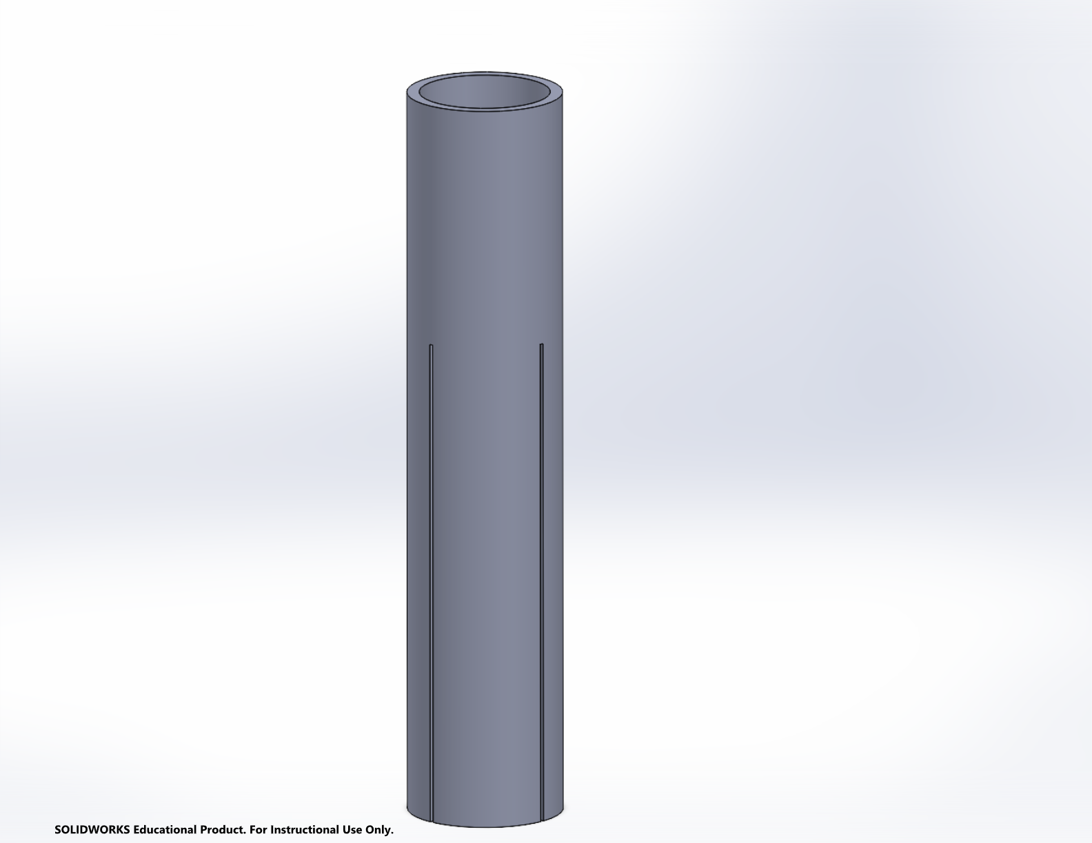
Motor casing / housing CAD
FIG. 09.A · Motor casing / housing — CADCAD
Sectioned SolidWorks view of the motor-retention housing showing internal retention geometry
FIG. 09.B · Sectioned retention interface — motor interface · retention featureCAD
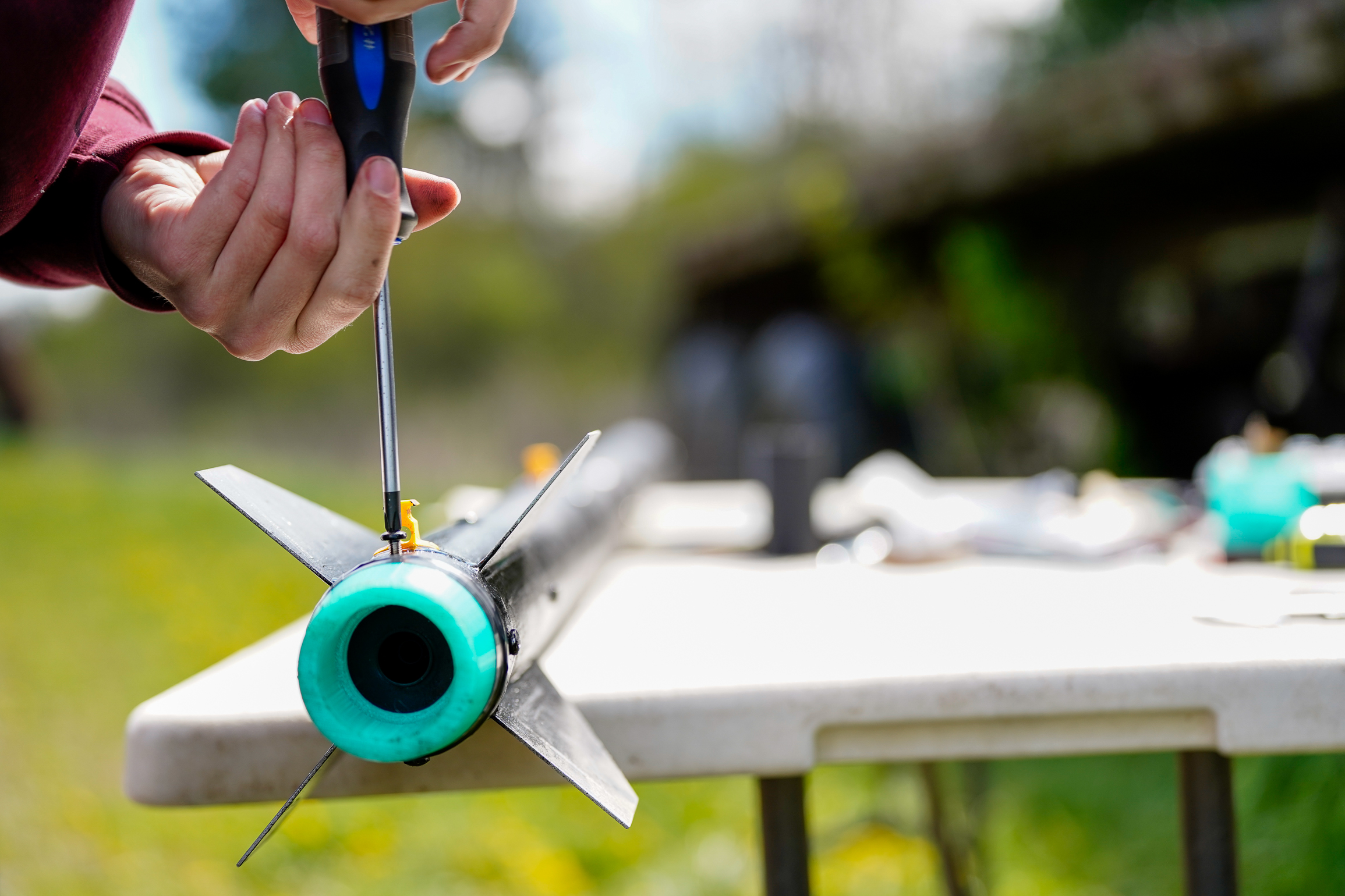
Aft section of the full-scale rocket on the launch rail, showing motor retainer
FIG. 09.C · Aft section during assemblyPHOTO
§ 06 — Recovery Ground Testing
Verification before flight

Verify recovery deployment on the ground before flight.

Before flight, the recovery system was exercised on the ground to verify deployment behavior end-to-end — from initiation through separation and parachute release. These tests informed the recovery-integration architecture and the changes carried between vehicles.

Ground testing was a critical part of the recovery engineering. It exposed integration issues while they could still be corrected on the bench, and directly increased confidence going into each flight.

FIG. 10 · Recovery deployment ground test — muted loopVIDEO
§ 07 — Iterative Flight-Test Program
Three vehicles, three lessons
TEST 01
Small Scale Vehicle I
Validate early architecture and gain high-power flight experience.
TEST 02
Small Scale Vehicle II
Revised recovery + experimental servo aft-fin control.
TEST 03
Full-Scale Vehicle
Integrate mature subsystems in the minimum-diameter architecture.
TEST 01 · SSV-I

Recovery failure and redesign.
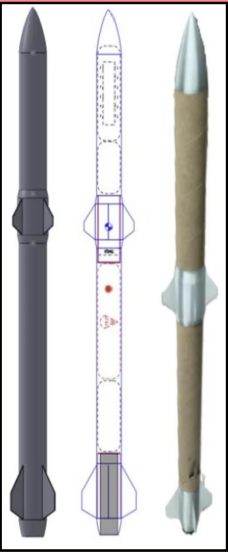
SSV-I and SSV-II configuration comparison showing aft-fin control addition
FIG. 11 · SSV configuration & assembled small-scale vehicleOpenRocket + Photo
Objective
Gain high-power flight experience and validate early vehicle/recovery concepts.
Result
Vehicle flew. Heat from the motor backcharge / ejection event damaged the recovery attachment, and the parachute separated during deployment.
Diagnosis
A thermal failure at the recovery attachment. The attachment was insufficiently protected from the thermal environment produced during the ejection event.
Change
Revised the recovery-attachment architecture and added heat-protection measures at the ejection interface (cellulose wadding and flame blanket), retaining nylon webbing in the load path. Planned to add live telemetry so flight data could still be collected even if the vehicle was lost in a subsequent failure. The revised recovery approach successfully deployed on the following SSV-II flight.
FAILURE
DIAGNOSIS
REDESIGN
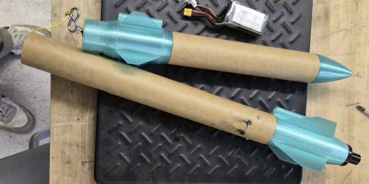
Small-scale development vehicles prior to flight
FIG. 11.B · Small-scale development vehicles — pre-flightPHOTO
TEST 02 · SSV-II

Active controls, stability, and scope reduction.

The second small-scale vehicle carried servo-driven aft-fin deflectors as an experimental active-control system. I worked heavily on the implementation because the mechanical hardware and control firmware had to be developed together.

What worked
  • Recovery system deployed
  • Active-control HW engaged
  • Flight data recovered
What was learned
  • Significant low-speed pitch deviation
  • Fin architecture introduced problems
  • Live telemetry unsuccessful
Engineering decision
Active control was removed from the full-scale vehicle after flight testing showed that sufficient safety and validation margin could not be achieved within the remaining budget and schedule.
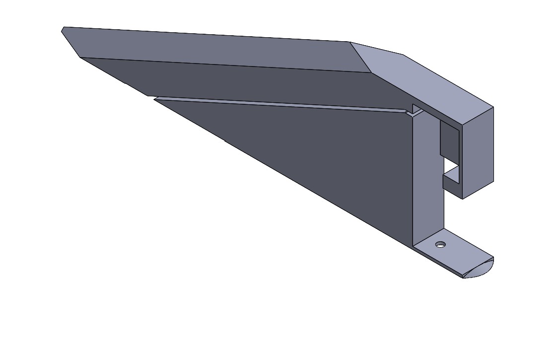
SSV-II aft-fin control system — CAD showing servo-driven deflector geometry
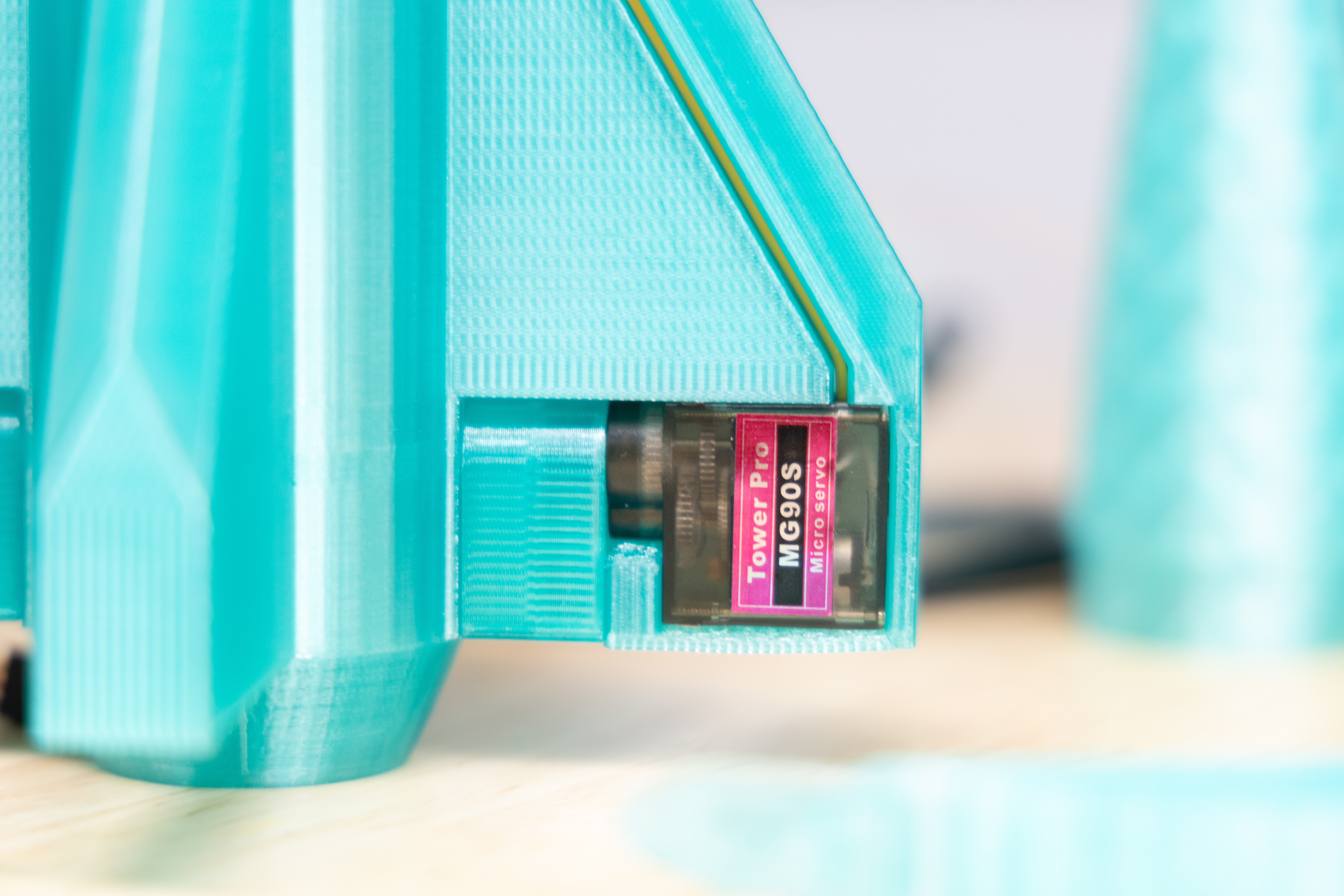
SSV-II aft fin housing with an MG90S micro-servo installed in the cutout, mating to the deflector actuator
FIG. 13 · SSV-II aft-fin control — CAD (13.A) → servo/fin hardware close-up (13.B, MG90S installed)CAD → PHOTO
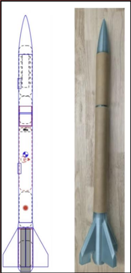
Small-scale vehicle OpenRocket configuration alongside the assembled small-scale airframe
FIG. 12 · SSV configuration progression — aft-fin control added on SSV-IIPOSTER
TEST 03 · FSV

Full-scale flight: stable ascent, recovery failure.

Objective
Integrate mature subsystems into the full-scale minimum-diameter vehicle.
Worked
Successful ignition and ascent. Generally stable ascent behavior; ascent broadly consistent with simulation for the motor flown.
Failed
Nose cone ejected, but the main parachute remained tightly packed inside the minimum-diameter airframe.
Hypothesis
Tight packaging plus flight acceleration increased compression and friction. Deployment gas escaped around the parachute rather than ejecting it.
Consequence
High-speed ground impact destroyed the avionics / data-storage hardware, preventing recovery of full-scale onboard flight data.
FIG. 14Deployment failure mode
01Packing volume approaches airframe ID; parachute is compressed.
02Boost acceleration further compresses the pack against restraint.
03At apogee, black-powder charge fires.
04Nose separates; parachute stays lodged.
05Deployment gas escapes around the pack instead of ejecting it.
06Descent under drag of open airframe only — high-speed impact.
§ 08 — Results
Honest accounting
DEMONSTRATED
  • Multiple flight vehicles designed and built
  • Repeated high-power flight testing
  • Embedded avionics integration
  • Sensor-based flight-data acquisition
  • Experimental servo-actuated flight controls
  • Recovery-system redesign and validation
  • Integration inside a constrained airframe
  • Propulsion retention
  • Iterative failure analysis
NOT FULLY DEMONSTRATED
  • Final 10,000-ft mission
  • Reliable full-scale recovery
  • Recovery of full-scale onboard data
  • Flight-ready active control on the final vehicle
Listed explicitly to distinguish demonstrated capability from unmet mission objectives.
§ 09 — Engineering Lessons
Five takeaways
01

Budget constraints can drive architecture.

Early composite-airframe cost constraints pushed the vehicle toward minimum diameter. Even after the material strategy changed, the resulting architecture continued to shape packaging and system risk.

02

System optimization beats subsystem optimization.

Improving one metric, whether drag, packaging density, or controllability, routinely created problems elsewhere. Judging the whole vehicle mattered more than winning a subsystem.

03

Flight test finds what ground test cannot.

Successful component tests did not guarantee system-level success under actual dynamic conditions. Deployment ultimately failed only under real flight loading.

04

Know when to remove scope.

Active control was removed when safety and validation confidence could not be reached inside the remaining budget and schedule.

05

Revisit architectural assumptions when constraints change.

The material change to kraft phenolic relaxed the original cost pressure that had forced minimum diameter, but the architecture inherited from that earlier decision was never revisited. Constraints move, and the design should be allowed to move with them.

§ 10 — What Failure Taught Us
Conclusion

The final flight did not end the way we intended. Recovery failed and the vehicle was lost. The purpose of an engineering test, though, is not simply to produce a successful demonstration. Its purpose is to reduce uncertainty and inform the next design.

This was the first year of this high-power rocket capstone effort at Syracuse. In under four months, and under a constrained budget, a five-person team progressed from an initial concept through design, fabrication, embedded systems development, ground testing, multiple flight tests, failure investigation, redesign, and the launch of a full-scale vehicle.

Across three vehicles we identified failure modes, changed designs, removed concepts we could not validate safely, and learned where the architecture needed to improve. None of that makes any single failure a success. It does mean each test produced information the next design would not have had otherwise.

Vehicle-by-vehicle
SSV-I
Exposed weaknesses in the recovery architecture.
SSV-II
Produced flight data and exposed limitations in the active-control approach.
Ground test
Verified recovery-system behavior end-to-end before flight.
FSV
Demonstrated that the team could integrate and launch the full vehicle, and revealed another recovery-system failure mode.
Continuity
The lessons, test experience, design knowledge, and documentation produced by this first-year effort are intended to support the Syracuse aerospace team continuing the capstone in 2026–2027. The next team will begin with those lessons instead of beginning from zero.
The vehicle was the first iteration of the program, not its final one.

Three vehicles, one budget-driven architecture, and a set of engineering lessons produced by flight testing.

← Previous
Northrop Grumman
Back to
Home →